Georeferencing is the name given to the process of transforming a scanned map or aerial photograph so it appears “in place” in GIS. By associating features on the scanned image with real world x and y coordinates, the software can progressively warp the image so it fits to other spatial datasets. In this example, a historic Toronto map will be georeferenced using a dataset of city streets so we can see what existed on the site of Robarts Library before it was built.
- Georeferencing requires a spatially referenced dataset that will be used to provide locations on the scanned map with their associated coordinates. In this example, we will match intersections represented on the scanned map with a shapefile of city streets.
- Below is a link to the .zip file that will be used during this tutorial. This file contains both the centreline_UTM17N.shp data file (showing city streets) as well as the V2-1910-172.tif image file (a scanned map of the block).
Please download and unzip the sample data. - Click the Add Data button in the Toolbar, this will allow you to browse to the folder location you have unzipped the ARCGIS_tutorialfiles.zip to.;
- Select the centreline_UTM17N.shp file and click OK to add dataset to the Table of Contents. Right-click on the name of the layer (centreline_UTM17N.shp) in the Table of Contents window, and select Label so street names appear on the map.
-
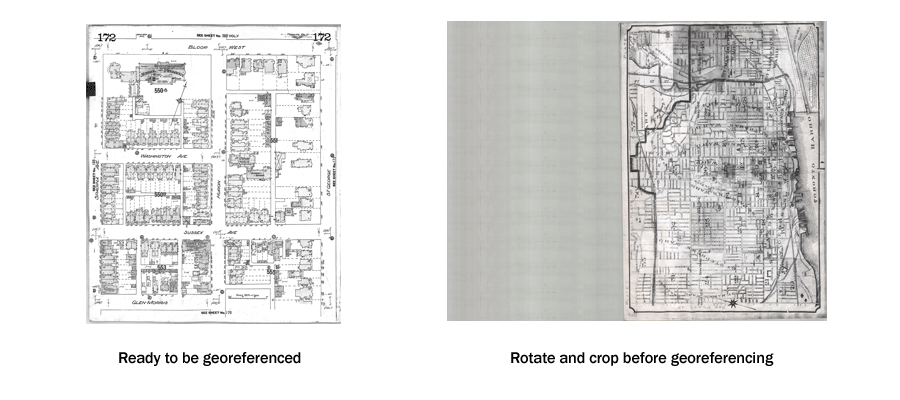
Before adding the raster file to be georeferenced make sure to open it in an image viewer or editor (e.g. IrfanView or Adobe Photoshop) to ensure there are no excess areas which can often occur with scanned images. For best results, the image should be rotated and cropped so it is oriented in the right direction and areas outside the edge of the map sheet have been removed. The image used in this tutorial (seen on the left, below) is ready to be georeferenced.

- Use the Add Data button to add the scanned map image (V2-1910-172.tif) to the map document. If asked if you would like to calculate statistics after adding the scanned image to ArcGIS Pro, select No:
-
Click the Imagery option in the main toolbar and select the Georeferencing option. this will switch the current toolbar options to the Georeferencing tool options:
- You will notice that while the raster file appears as a layer in the Table of Contents, it is not immediately visible on the screen. To make the image visible click the Fit to Display option on the left of the toolbar.
- Use the Zoom tool to zoom in to the University of Toronto area in the road network file, shown here in the highlighted rectangle on the map below:

-
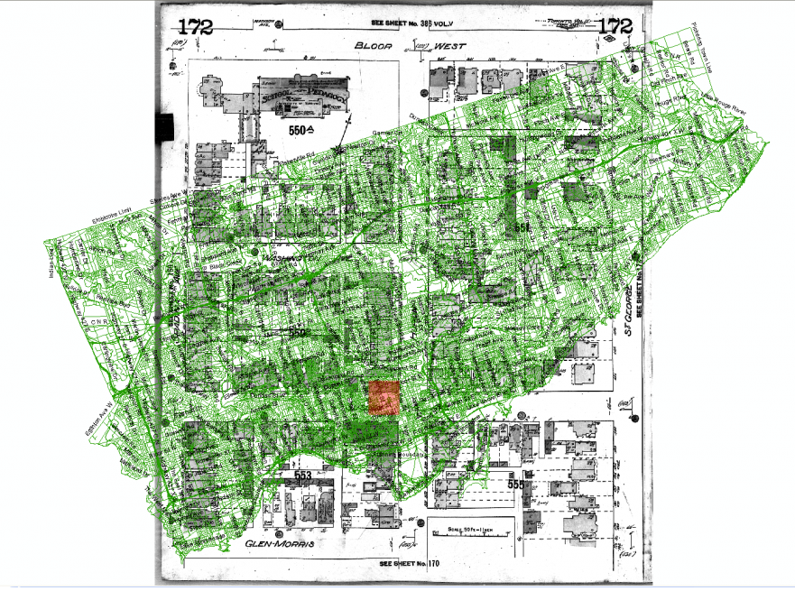
Use the Zoom In, Zoom Out and Pan tools to approximately centre the streets between Spadina Ave., Bloor St., St. George St., and Harbord St. in the map view. The appropriate section of the digital road network file now fills the screen yet the raster image of the fire insurance plan does not match in scale or orientation.
-
There are two methods in which you can bring the scales of both the digital map data and the scanned image more in line with each other. The first is to use the same method as outlined in Step 9 Georeferencing > Fit to Display. the second is to use the Rotate, Shift and Scale commands located on the Georeferencing toolbar which allows for the manual transformation of the source layer. Regardless of the method used, the end result should look similar to the second image below prior to moving on with the next steps in this tutorial.
You can now begin georeferencing the map - In order to increase accuracy in selecting your control points it is best to turn on the Vertex Snapping option in the snapping toolbar. This toolbar will not be visible at first, you may find it by clicking on Edit, identify Snapping, and from the dropdown menu, select the rectangle “Vertex”.
- Another option which can be selected at this time is the Auto-Georeference option which can be found back in the Georeference toolbar. This will automatically update the display and adjust the raster image with each new control point added. It is recommended that the Auto-Adjust option be selected for most GIS needs so that you can monitor the georeferencing process in real time.
- Click on the Add Control Points button in the Georeferencing toolbar. This tool allows you to associate points in a scanned map or aerial image with their real-world spatial coordinates within your GIS.
-
To add a Control Point to your map, first click on a location on the scanned map (a red square will appear as seen in the first image below), then click on the corresponding location in your street dataset to associate the two (a blue box should appear as you hover over the associated point as shown in the second image below). Once clicked in place, the control point will be indicated. In this example, we will match the centre of the intersection of streets on the scanned map to the intersection of the same streets in our geospatial data, represented as line features in the spatial dataset
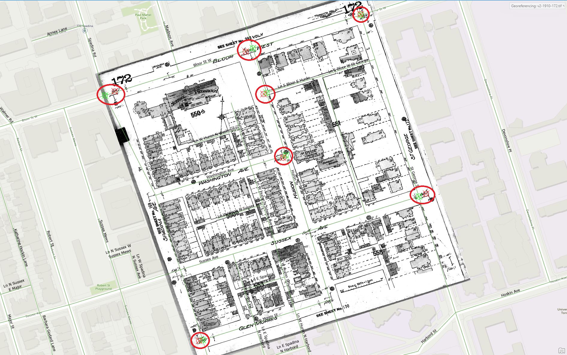
- Continue adding control points until the raster image moves into place geographically, aligning itself with the digital data map. You will notice that after two control points were added the image automatically warped into position, in most cases several more control points should be added to increase the accuracy of the overlay. Select areas close to four corners of the map area between the four corner points which should ensure that all points are georeferenced evenly
-
If at any time you need to edit or delete any control points collected, this can be done by accessing the Control Points Table button on the Georeferencing taskbar (shown below). This table displays the Control Point(s) information.
Both the Source and Map points can be edited by double-clicking on the values in the table.
- With the addition of control points at intersections and the auto-adjustment of the raster image to the digital dataset, your image should now look very similar to the image below:
- Using the Save tool in the Georeferencing Toolbar will store the transformation information with the raster file, which can be internal or external depending on the type of raster dataset being used (ie. for the current raster dataset, that is a TIFF file, the transformation will be stored in what is known as a world file, with a .tfw or .tfwx extension)
-
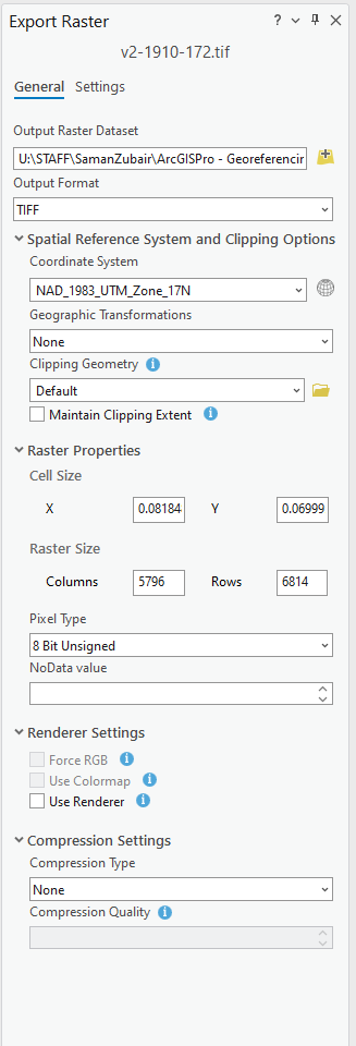
Using the Save as New command will open the Export Raster tool on the right of the screen. This will allow you to create a new raster dataset that is georeferenced using both map co-ordinates and spatial references which can be saved in a number of different formats (BIL, BIP, BMP, DAT, GIF, TIFF, ESRI GRID, IMG, JPEG, JPEG 2000, PNG). This command can be useful if you wish to perform further analysis with the raster dataset or use it in an external program that does not recognize the external georeference information created in the ArcGIS world file (eg. tfwx).


